

Why simulate cells
A real BMS has to handle thermal runaway protection, state-of-charge estimation, cell-balancing, and overvoltage / overcurrent shutoff — and it needs to handle them correctly long before any real cells are connected. Validating those behaviours on actual lithium cells is slow, hardware-destructive when things go wrong, and impossible to repeat exactly across test runs.
This demo replaces the cells with a controllable bi-directional power supply. Every "cell voltage" is now a software-controlled variable. Every fault scenario — undervoltage, overtemperature, runaway charge — can be triggered on demand, repeatedly, without risk.
The hardware
LTC6812 cell measurement PCB — Linear Technology's standard battery monitoring IC. Reads up to 15 cell voltages plus temperature inputs, supports passive cell balancing, and daisy-chains over IsoSPI for stacking longer packs.
SparkBit — a Tech42 industrial computer based on the Texas Instruments AM625. Linux, 3× CAN, SPI/I2C/UART, and an IsoSPI transceiver to talk to the LTC6812 directly. Reads the measurements off the LTC6812 and republishes them on CAN.
Itech M3412 — a bi-directional bench power supply controllable over CANopen. In this setup it doesn't supply real battery power; it generates the voltages each "cell" should be at. Driving its setpoint from MACS lets us simulate charge, discharge, drift, and fault conditions against the same harness a real pack would use.
How it fits together
The signal path is: Itech M3412 → simulated cells → LTC6812 → IsoSPI → SparkBit → CAN → MACS → Voltage Setpoint → Itech M3412. The loop closes back through MACS, which is where the actual battery control logic lives.
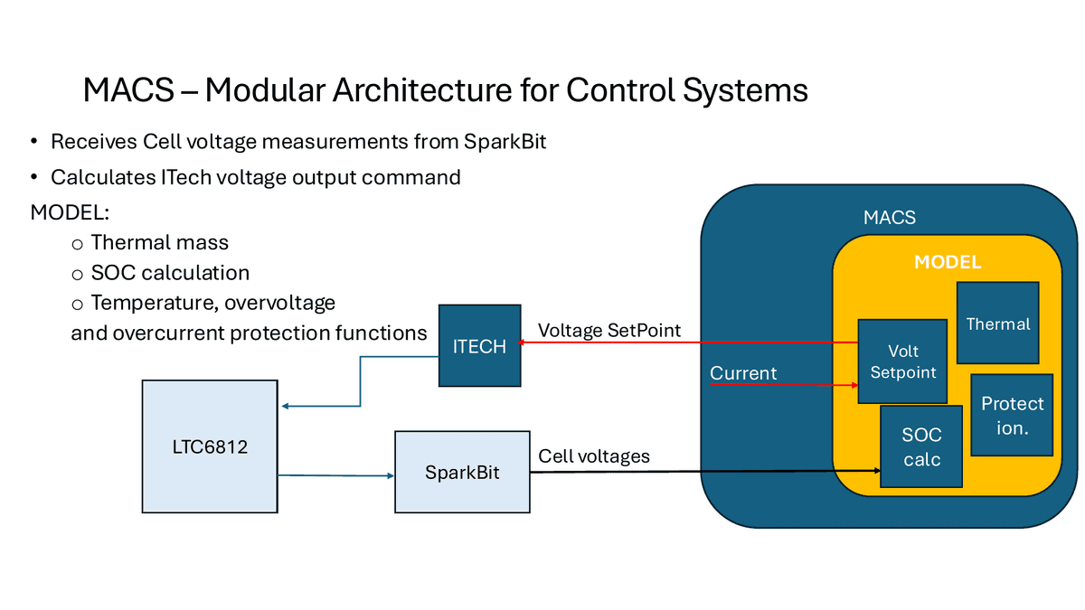
The MACS model contains:
- Thermal mass — tracks heat generation and dissipation per cell
- SOC calculation — coulomb-counting plus voltage-based correction
- Voltage setpoint — what the Itech should drive each cell to next
- Protection — temperature, overvoltage, and overcurrent limits with shutdown logic
Each block is a node in the MACS visual designer, so individual algorithms can be swapped or tuned without touching the rest of the pipeline. Add a Kalman-filter SOC estimator, swap the protection logic, plug in a Python node for an ML-based capacity estimator — all live, without recompiling.
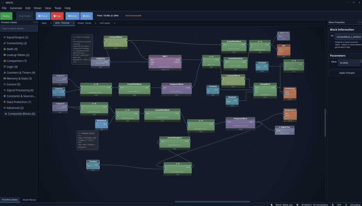
The screenshot above shows the SOC + Thermal subsheet running in simulation — 35 blocks, 35 connections, simulating at 10 Hz. Constants like cell capacity, thermal mass, and ambient temperature are live-editable from the Block Properties panel. The same sheet can be deployed to the SparkBit running on the bench, or to a production controller, without modification.
Why this matters
The same MACS configuration that runs against the simulated bench runs unchanged when the Itech is replaced with a real pack. The control software doesn't know — and doesn't need to know — whether the voltages it's reading came from cells or from a power supply pretending to be cells. That's the point of the architecture: validate your algorithms in a safe, repeatable, fully-instrumented environment, then deploy the exact same model to production hardware.
For BMS development teams, this collapses the painful gap between simulation and real-hardware testing into a single workflow.